
QUINT4-PS/24DC/48DC/5/PT
Product ID:17156
Updated: 2026/10/13
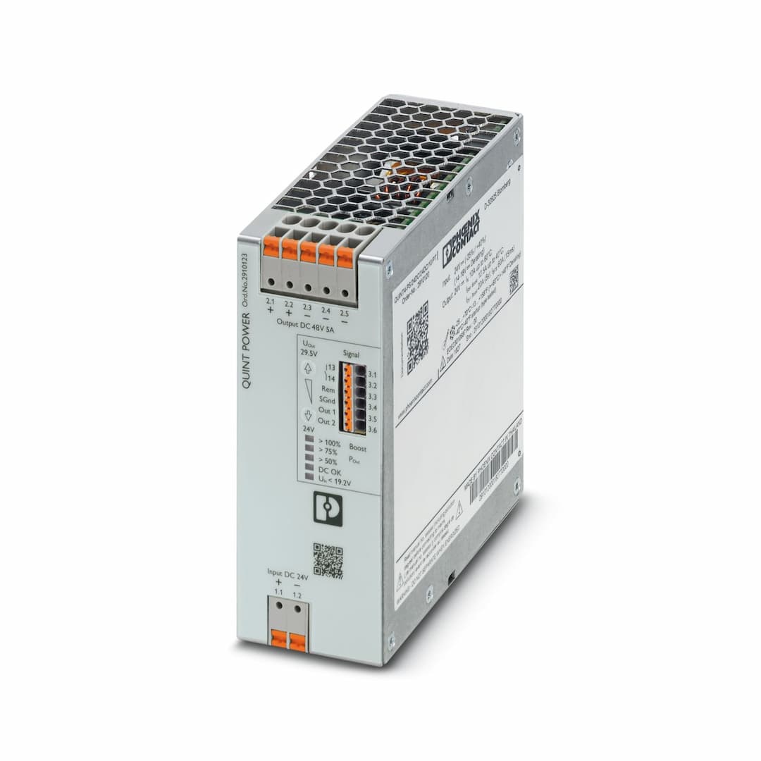
Key Features
- 1Easy system expansion and reliable heavy load startup.
- 2Preventive function monitoring reports critical operating states before errors occur.
- 3Ready from a batch quantity of just 1.
- 4Typical efficiency of 94% (24 V DC).
- 5Push-in connection and flexible conductor cross sections for easy installation.
Need a quote? Enter your quantity and get pricing fast.
Qty
Technical Specifications
Detailed engineering parameters
| Parameter | Value | Parameter | Value |
|---|---|---|---|
| Nominal input voltage range | 24 V DC | Input voltage range | 24 V DC -25 % ... +40 % |
| Wide-range input | no | Electric strength, max. | 35 V DC (60 s) |
| Inrush current | typ. 1 A | Inrush current integral (I | < 0.01 A |
| Inrush current limitation | 1 A (after 1 ms) | Mains buffering time | typ. 16 ms (24 V DC) |
| Current consumption | 13.8 A (24 V DC) | Typical response time | 300 ms (from SLEEP MODE) |
| Switch-on time | < 1 s | Input fuse | 30 A (slow-blow, internal) |
| Recommended breaker for input protection | 16 A ... 20 A (Characteristic B, C, D, K or comparable) | Efficiency | typ. 94 % (24 V DC) |
| Output characteristic | U/I Advanced
Smart HICCUP
FUSE MODE | Nominal output voltage | 48 V DC |
| Setting range of the output voltage (U | 48 V DC ... 56 V DC (> 48 V constant capacity) | Nominal output current (I | 5 A |
| Static Boost (I | 6.25 A | Dynamic Boost (I | 10 A (5 s) |
| Selective Fuse Breaking (I | 30 A (15 ms) | Magnetic circuit breaker tripping | A1...A6 / B2 / C1...C2 / Z1...Z6 |
| Short-circuit-proof | yes | No-load proof | yes |
| Output power (P | 240 W | Output power (P | 300 W |
| Output power (P | 480 W (5 s) | Feedback voltage resistance | ≤ 60 V DC |
| Protection against overvoltage at the output (OVP) | ≤ 60 V DC | Residual ripple | < 50 mV |
| Control deviation | < 3 % (change in load, static 10 % ... 90 %) | Control deviation | < 3 % (change in load, static 10 % ... 90 %) |
| Control deviation | < 3 % (change in load, static 10 % ... 90 %) | Rise time | < 100 ms (U |
| Connection in series | yes | Maximum no-load power dissipation | < 4 W |
| Power loss nominal load max. | < 16 W | Power dissipation SLEEP MODE | < 2 W |
| Connection in parallel | yes, for redundancy and increased capacity | Position | 1.x |
| Connection method | Push-in connection | rigid | 0.2 mm² ... 6 mm² |
| flexible | 0.2 mm² ... 6 mm² | flexible with ferrule without plastic sleeve | 0.2 mm² ... 4 mm² |
| flexible with ferrule with plastic sleeve | 0.2 mm² ... 4 mm² | rigid (AWG) | 24 ... 10 |
| Stripping length | 10 mm | Position | 2.x |
| Connection method | Push-in connection | rigid | 0.2 mm² ... 6 mm² |
| flexible | 0.2 mm² ... 6 mm² | flexible with ferrule without plastic sleeve | 0.2 mm² ... 4 mm² |
| flexible with ferrule with plastic sleeve | 0.2 mm² ... 4 mm² | rigid (AWG) | 24 ... 10 |
| Stripping length | 10 mm | Position | 3.x |
| Connection method | Push-in connection | rigid | 0.2 mm² ... 1 mm² |
| flexible | 0.2 mm² ... 1.5 mm² | flexible with ferrule without plastic sleeve | 0.2 mm² ... 1.5 mm² |
| flexible with ferrule with plastic sleeve | 0.2 mm² ... 0.75 mm² | rigid (AWG) | 24 ... 16 |
| Stripping length | 8 mm | Types of signaling | LED
Floating signal contact
Active signal output Out1 (digital, configurable)
Active signal output Out2 (analog, configurable)
Remote contact
Signal ground SGnd |
| Signal threshold | > 100 % (LED lights up yellow, output power > 240 W)
> 75 % (LED lights up green, output power > 180 W)
> 50 % (LED lights up green, output power > 120 W)
> 0.9 x U
< 0.9 x U
> 0.8 x U
< 0.8 x U | Connection labeling | 3.3 + |
| Function | Output power ON/OFF (remote) | Default | Output power ON (>40 kΩ/24 V DC/open bridge between REM and SGnd) |
| Connection labeling | 3.5 + | Digital | 0 V DC
24 V DC
20 mA |
| Default | U | Signal option | Output voltage
Output current
Output power
Operating hours
Early warning of high temperatures
OVP voltage limitation active |
| Connection labeling | 3.6 + | Digital | 0 V DC
24 V DC
20 mA |
| Default | Output power | Signal option | Output voltage
Output current
Operating hours
Early warning of high temperatures
OVP voltage limitation active |
| Analog | 4 mA ... 20 mA ±5 % (Load ≤400 Ω) | Signal option | Output voltage
Output current
Output power |
| Connection labeling | 3.1, 3.2 | Switch contact (floating) | floating |
| Digital | 24 V DC
1 A
30 V AC
0.5 A | Default | Output voltage |
| Signal option | Output current
Output power
Operating hours
Early warning of high temperatures
OVP voltage limitation active
U | Connection labeling | 3.4 + |
| Function | Signal ground | Reference potential | to OUT1, OUT2, REM |
| Number of phases | 1.00 | Insulation voltage input/output | 4 kV DC (type test)
2 kV DC (routine test) |
| Switching frequency | 190.00 kHz ... 220.00 kHz (Auxiliary converter stage)
67.00 kHz ... 135.00 kHz (Main converter stage) | Product type | DC/DC converters |
| Product family | QUINT POWER | MTBF (IEC 61709, SN 29500) | > 1369000 h (25 °C)
> 793000 h (40 °C)
> 328000 h (60 °C) |
| Article revision | 02 | Protection class | Special with SELV input and output |
| Degree of pollution | 2 | Current | 2.5 A |
| Temperature | 40 °C | Time | 359600 h |
| Additional text | 24 V DC | Current | 5 A |
| Temperature | 40 °C | Time | 176200 h |
| Additional text | 24 V DC | Current | 5 A |
| Temperature | 30 °C | Time | 352500 h |
| Additional text | 24 V DC | Width | 50 mm |
| Height | 130 mm | Depth | 125 mm |
| Width | 122 mm | Height | 130 mm |
| Depth | 53 mm | Installation distance right/left (active) | 15 mm / 15 mm (≤ 70 °C) |
| Installation distance right/left (passive) | 0 mm / 0 mm (≤ 70 °C) | Installation distance top/bottom (active) | 50 mm / 50 mm (≤ 70 °C) |
| Installation distance top/bottom (passive) | 50 mm / 50 mm (≤ 70 °C) | Mounting type | DIN rail mounting |
| Assembly note | alignable: P | With protective coating | no |
| Flammability rating according to UL 94 (housing / terminal blocks) | V0 | Housing material | Metal |
| Hood version | Stainless steel X6Cr17 | Side element version | Aluminum |
| Degree of protection | IP20 | Ambient temperature (operation) | -25 °C ... 70 °C (> 60 °C Derating: 2,5 %/K) |
| Ambient temperature (storage/transport) | -40 °C ... 85 °C | Ambient temperature (start-up type tested) | -40 °C |
| Maximum altitude | ≤ 5000 m (> 2000 m, observe derating) | Climatic class | 3K22 (in accordance with EN 60721-3-3) |
| Max. permissible relative humidity (operation) | ≤ 95 % (at 25 °C, non-condensing) | Shock | 18 ms, 30g, in each space direction (according to IEC 60068-2-27) |
| Vibration (operation) | 5 Hz ... 100 Hz resonance search 2.3g, 90 min., resonance frequency 2.3g, 90 min. (according to DNV GL Class C) | Temp code | T4 (-25 ... +70 °C; > 60 °C, Derating: 2,5 %/K) |
| EN 61010-1 | II (≤ 5000 m) | EN 62477-1 | III (≤ 2000 m) |
| Standard designation | Electrical safety (of control and regulation devices) | Standards/specifications | IEC 61010-1 |
| Standard designation | Protective extra-low voltage | Standards/specifications | EN 61010-1 (SELV)
IEC 61010-2-201 (PELV) |
| Standard designation | Mains variation/undervoltage | Standards/specifications | EN 61000-4-29 |
| Standard designation | Railway applications | Standards/specifications | EN 50121-3-2
IEC 62236-3-2
EN 50121-5
IEC 62236-5 |
| Identification | UL Listed UL 61010-1 | Identification | UL Listed UL 61010-2-201 |
| Identification | UL 121201 & CSA C22.2 No. 213-17 Class I, Division 2, Groups A, B, C, D T4 (Hazardous Location) | Identification | CAN/CSA-C22.2 No. 61010-1-12 |
| Identification | CAN/CSA C22.2 No. 61010-2-201:18 | Identification | Type tested (type approved) |
| Identification | CB scheme (IEC 61010-1, IEC 61010-2-201) | Identification | DNV |
| Identification | BV | Identification | NK |
| Identification | LR | Electromagnetic compatibility | Conformance with EMC Directive 2014/30/EU |
| Low Voltage Directive | Conformance with Low Voltage Directive 2014/35/EC | EMC requirements for noise emission | EN 61000-6-3
EN 61000-6-4 |
| EMC requirements for noise immunity | EN 61000-6-1
EN 61000-6-2 | EMC requirements, power plant | IEC 61850-3
EN 61000-6-5 |
| Conducted noise emission | EN 55016
EN 61000-6-3 (Class B) | Noise emission | Additional basic standard EN 61000-6-5 (immunity in power station), IEC/EN 61850-3 (energy supply) |
| Noise emission | EN 55016
EN 61000-6-3 (Class B) | DNV GL conducted interference | Class B |
| Additional text | Bridge and deck area | DNV GL noise radiation | Class B |
| Additional text | Bridge and deck area | Standards/regulations | EN 61000-4-2 |
| Contact discharge | 8 kV (Test Level 4) | Discharge in air | 15 kV (Test Level 4) |
| Comments | Criterion A | Standards/regulations | EN 61000-4-3 |
| Frequency range | 80 MHz ... 1 GHz | Test field strength | 20 V/m (Test Level 3) |
| Frequency range | 1 GHz ... 6 GHz | Test field strength | 10 V/m (Test Level 3) |
| Comments | Criterion A | Standards/regulations | EN 61000-4-4 |
| Input | 2 kV (Test Level 3 - asymmetrical) | Output | 2 kV (Test Level 3 - asymmetrical) |
| Signal | 2 kV (Test Level 4 - asymmetrical) | Comments | Criterion A |
| Standards/regulations | EN 61000-4-5 | Input | 1 kV (Test Level 3 - symmetrical)
2 kV (Test Level 3 - asymmetrical) |
| Output | 1 kV (Test Level 3 - symmetrical)
2 kV (Test Level 3 - asymmetrical) | Signal | 2 kV (Test Level 3 - asymmetrical) |
| Comments | Criterion A | Standards/regulations | EN 61000-4-6 |
| I/O/S | asymmetrical | Frequency range | 0.15 MHz ... 80 MHz |
| Comments | Criterion A | Voltage | 10 V (Test Level 3) |
| Standards/regulations | EN 61000-4-8 | Frequency | 16.7 Hz
50 Hz
60 Hz |
| Test field strength | 100 A/m | Additional text | 60 s |
| Comments | Criterion A | Frequency | 50 Hz
60 Hz |
| Frequency range | 50 Hz ... 60 Hz | Test field strength | 1 kA/m |
| Additional text | 3 s | Comments | Criterion A |
| Frequency | 0 Hz | Test field strength | 300 A/m |
| Additional text | DC, 60 s | Comments | Criterion A |
| Standards/regulations | EN 61000-4-29 | Voltage | 24 V DC |
| Voltage dip | 70 % | Time | 100 ms |
| Additional text | Test Level 2 | Comments | Criterion A |
| Voltage dip | 40 % | Time | 100 ms |
| Additional text | Test Level 2 | Comments | Criterion B |
| Voltage dip | 0 % | Time | 50 ms |
| Additional text | Test Level 2 | Comments | Criterion B |
| Standards/regulations | EN 61000-4-9 | Test field strength | 1000 A/m |
| Comments | Criterion A | Standards/regulations | EN 61000-4-16 |
| Test level 1 | 15 Hz 150 Hz (Test Level 3) | Voltage | 10 V 1 V |
| Test level 2 | 150 Hz 1.5 kHz (Test Level 3) | Voltage | 1 V |
| Test level 3 | 1.5 kHz 15 kHz (Test Level 3) | Voltage | 1 V 10 V |
| Test level 4 | 15 kHz 150 kHz (Test Level 3) | Voltage | 10 V |
| Test level 5 | 16.7 Hz 50 Hz 60 Hz 150 Hz 180 Hz (Test Level 3) | Voltage | 10 V (Permanent) |
| Test level 6 | 0 Hz 16.7 Hz 50 Hz 60 Hz (Test Level 3) | Voltage | 100 V (1 s) |
| Comments | Criterion A | Standards/regulations | EN 61000-4-17 |
| Alternating component | 15 % (U | Frequency | 50 Hz
100 Hz
150 Hz |
| Comments | Criterion A | Alternating component | 14 % (U |
| Frequency | 300 Hz | Comments | Criterion A |
| Standards/regulations | EN 61000-4-18 | Input, output (test level 1) | 100 kHz 1 MHz (Test Level 2 - symmetrical) |
| Voltage | 0.5 kV | Input, output (test level 2) | 100 kHz 1 MHz (Test Level 2 - asymmetrical) |
| Voltage | 1 kV | Input, output (test level 3) | 10 MHz (Test Level 2 - asymmetrical) |
| Voltage | 0.5 kV | Signals (test level 1) | 100 kHz 1 MHz (Test Level 2 - symmetrical) |
| Voltage | 0.5 kV | Signals (test level 2) | 100 kHz 1 MHz (Test Level 2 - asymmetrical) |
| Voltage | 1 kV | Comments | Criterion A |
| Standards/regulations | EN 61000-4-10 | Test field strength | 100 A/m |
| Test level 1 | 100 kHz | Test field strength | 100 A/m |
| Test level 2 | 1 MHz | Comments | Criterion A |
| Criterion A | Normal operating behavior within the specified limits. | Criterion B | Temporary impairment to operational behavior that is corrected by the device itself. |
| Criterion C | Temporary adverse effects on the operating behavior, which the device corrects automatically or which can be restored by actuating the operating elements. |
Specifications may be subject to change without notice
Still deciding on QUINT4-PS/24DC/48DC/5/PT?
Our engineers can confirm stock, price, and lead time for this Phoenix Contact part.
Get a no-obligation quote in 1 minute.