
TRIO-PS-2G/3AC/24DC/40
Product ID:17231
Updated: 2026/10/13
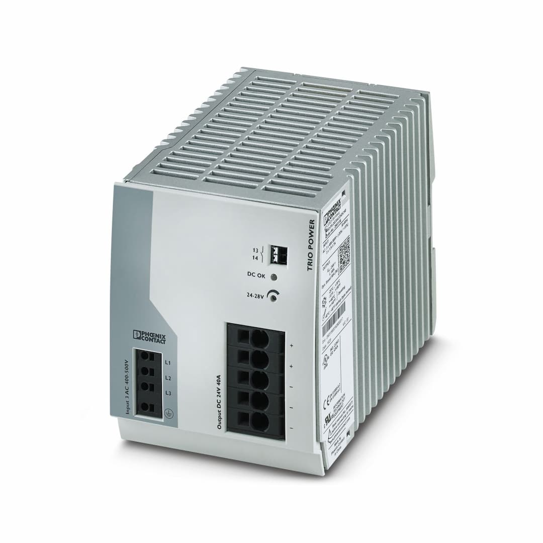
Key Features
- 1Robust Design: Electrically and mechanically robust design ensures reliable supply under challenging ambient conditions.
- 2Dynamic Boost: Provides 150% of nominal current for five seconds to absorb starting currents and short overload situations.
- 3Tool-Free Connection: Fast and tool-free wiring with push-in connection technology for solid and stranded conductors.
- 4Wide Temperature Range: Operates from -25°C to +70°C and starts at -40°C, ensuring flexibility in various environments.
- 5High Efficiency: Efficiency of up to 93% (400 V AC) and low power loss, making it an energy-efficient solution.
Need a quote? Enter your quantity and get pricing fast.
Qty
Technical Specifications
Detailed engineering parameters
| Parameter | Value | Parameter | Value |
|---|---|---|---|
| Network type | Star network | Nominal input voltage range | 3x 400 V AC ... 500 V AC |
| Input voltage range | 3x 400 V AC ... 500 V AC -20 % ... +15 % | Typical national grid voltage | 3x 400 V AC
3x 480 V AC |
| Voltage type of supply voltage | AC | Inrush current integral (I | ≤ 1.1 A |
| Inrush current limitation | 35 A (after 1 ms) | AC frequency range | 50 Hz ... 60 Hz |
| Frequency range (f | 50 Hz ... 60 Hz ±5 Hz | Mains buffering time | > 10 ms (400 V AC)
> 20 ms (480 V AC) |
| Current consumption | 3x 1.9 A (400 V AC)
3x 1.7 A (500 V AC) | Nominal power consumption | 1335.1 VA |
| Protective circuit | Transient surge protection; Varistor | Power factor (cos phi) | 0.77 |
| Typical response time | < 1 s | Input fuse | 6.3 A (internal (device protection)) |
| Recommended breaker for input protection | 10 A ... 16 A (Characteristics B, C, D, K) | Discharge current to PE | < 3.5 mA
< 2.5 mA (550 V AC, 60 Hz) |
| POWER factor | > 0.7 (400 V AC)
> 0.7 (480 V AC) | Efficiency | typ. 93 % (400 V AC)
typ. 93.3 % (480 V AC) |
| Output characteristic | U/I with dynamic load reserve | Nominal output voltage | 24 V DC ±1 % |
| Setting range of the output voltage (U | 24 V DC ... 28 V DC (> 24 V DC, constant capacity restricted) | Nominal output current (I | 40 A |
| Dynamic Boost (I | 60 A (5 s) | Derating | > 60 °C ... 70 °C (2.5 %/K) |
| POWER factor | > 0.7 (400 V AC)
> 0.7 (480 V AC) | Feedback voltage resistance | < 35 V |
| Protection against overvoltage at the output (OVP) | ≤ 30 V DC | Control deviation | < 1 % (change in load, static 10 % ... 90 %)
< 3 % (Dynamic load change 10 % ... 90 %, 10 Hz)
< 0.1 % (change in input voltage ±10 %) |
| Residual ripple | ≤ 50 mV | Short-circuit-proof | yes |
| No-load proof | yes | Output power | 960 W
1440 W |
| Maximum no-load power dissipation | typ. 14 W (400 V AC)
typ. 17 W (480 V AC) | Power loss nominal load max. | < 70 W (480 V AC)
typ. 72 W (480 V AC) |
| Short-circuit current | < 48 A DC (Permanent) | Rise time | ≤ 1 s (U |
| Connection in parallel | yes, for redundancy and increased capacity | Connection in series | yes |
| Continuous load current | 100 mA | Default | closed |
| Digital | 30 V AC 30 V DC 100 mA | Connection method | Push-in connection |
| Conductor cross section, rigid min. | 0.2 mm² | Conductor cross section, rigid max. | 4 mm² |
| Conductor cross section flexible min. | 0.2 mm² | Conductor cross section flexible max. | 2.5 mm² |
| Single conductor/terminal point, stranded, with ferrule, min. | 0.2 mm² | Single conductor/terminal point, stranded, with ferrule, max. | 2.5 mm² |
| Conductor cross section AWG min. | 24 | Conductor cross section AWG max. | 12 |
| Stripping length | 10 mm | Connection method | Push-in connection |
| Conductor cross section, rigid min. | 0.75 mm² | Conductor cross section, rigid max. | 16 mm² |
| Conductor cross section flexible min. | 0.75 mm² | Conductor cross section flexible max. | 10 mm² |
| Single conductor/terminal point, stranded, with ferrule, min. | 0.75 mm² | Single conductor/terminal point, stranded, with ferrule, max. | 10 mm² |
| Conductor cross section AWG min. | 20 | Conductor cross section AWG max. | 4 |
| Stripping length | 18 mm | Connection method | Push-in connection |
| Conductor cross section, rigid min. | 0.2 mm² | Conductor cross section, rigid max. | 1.5 mm² |
| Conductor cross section flexible min. | 0.2 mm² | Conductor cross section flexible max. | 1.5 mm² |
| Single conductor/terminal point, stranded, with ferrule, min. | 0.2 mm² | Single conductor/terminal point, stranded, with ferrule, max. | 1.5 mm² |
| Conductor cross section AWG min. | 24 | Conductor cross section AWG max. | 16 |
| Stripping length | 8 mm | Types of signaling | LED
Floating signal contact |
| Signalization designation | DC OK | Status display | LED |
| Color | green | DC OK | U |
| Number of phases | 3.00 | Insulation voltage input/output | 3 kV AC (type test)
1.5 kV AC (routine test) |
| Product type | Power supply | Product family | TRIO POWER |
| MTBF (IEC 61709, SN 29500) | > 1730000 h (25 °C)
> 1051000 h (40 °C)
> 510000 h (60 °C) | Article revision | 04 |
| Protection class | I (in closed control cabinet) | Degree of pollution | 2 |
| Width | 110 mm | Height | 130 mm |
| Depth | 160 mm | Installation distance right/left | 0 mm / 0 mm |
| Installation distance top/bottom | 50 mm / 50 mm | Mounting type | DIN rail mounting |
| Assembly note | alignable: horizontally 0 mm (≤ 40 °C) 10 mm (≤ 70 °C), vertically 50 mm | Mounting position | horizontal DIN rail NS 35, EN 60715 |
| With protective coating | no | Flammability rating according to UL 94 (housing / terminal blocks) | V0 |
| Housing material | Metal | Type of housing | Aluminum (AlMg3) |
| Hood version | Polycarbonate | Degree of protection | IP20 |
| Ambient temperature (operation) | -25 °C ... 70 °C (> 60 °C Derating: 2,5 %/K) | Ambient temperature (storage/transport) | -40 °C ... 85 °C |
| Ambient temperature (start-up type tested) | -40 °C | Maximum altitude | ≤ 4000 m (> 2000 m, Derating: 10 %/1000 m) |
| Climatic class | 3K3 (in acc. with EN 60721) | Max. permissible relative humidity (operation) | ≤ 95 % (at 25 °C, non-condensing) |
| Shock | 11 ms, 15 g, in each space direction (according to IEC 60068-2-27) | Vibration (operation) | DNV GL CG-0339 / Class B |
| Rail applications | EN 50121-4 | Standard – Electronic equipment for use in electrical power installations and their assembly into electrical power installations | EN 50178/VDE 0160 (PELV) |
| Standard – Limitation of mains harmonic currents | EN 61000-3-2 | Standard - Electrical safety | IEC 62368-1 (SELV) |
| Standard – Safety extra-low voltage | IEC 62368-1 (SELV) und EN 60204-1 (PELV) | Standard - Safe isolation | DIN VDE 0100-410 |
| Standard - Safety of power supply units up to 1100 V (insulation distances) | DIN EN 61558-2-16 | EN 60950-1 | II |
| EN 62477-1 | III | UL approvals | UL Listed UL 508
UL/C-UL Recognized UL 60950-1 |
| SIL in accordance with IEC 61508 | 0 | Electromagnetic compatibility | Conformance with EMC Directive 2014/30/EU |
| Low Voltage Directive | Conformance with Low Voltage Directive 2014/35/EC | EMC requirements for noise emission | EN 61000-6-3
EN 61000-6-4 |
| EMC requirements for noise immunity | EN 61000-6-1
EN 61000-6-2 | Conducted noise emission | EN 55016
EN 61000-6-3 (Class B) |
| Noise emission | EN 55011 (EN 55022) | Noise emission | EN 55016
EN 61000-6-3 (Class B) |
| Frequency range | Class A, B | Frequency range | 0 kHz ... 2 kHz |
| Standards/regulations | EN 61000-4-2 | Contact discharge | 6 kV (Test Level 3) |
| Discharge in air | 8 kV (Test Level 3) | Comments | Criterion A |
| Standards/regulations | EN 61000-4-3 | Frequency range | 80 MHz ... 6 GHz |
| Test field strength | 10 V/m (Test Level 3) | Frequency range | 80 MHz ... 6 GHz |
| Test field strength | 10 V/m (Test Level 3) | Frequency range | 80 MHz ... 6 GHz |
| Test field strength | 10 V/m (Test Level 3) | Comments | Criterion A |
| Standards/regulations | EN 61000-4-4 | Input | 4 kV (Test Level 3 - asymmetrical) |
| Output | 2 kV (Test Level 3 - asymmetrical) | Signal | 2 kV (Test Level 3 - asymmetrical) |
| Comments | Criterion A | Standards/regulations | EN 61000-4-5 |
| Input | 1 kV (Test Level 1 - symmetrical)
2 kV (Test Level 1 - asymmetrical) | Output | 0.5 kV (Test Level 1 - symmetrical)
0.5 kV (Test Level 1 - asymmetrical) |
| Signal | 1 kV (Test Level 2 - asymmetrical) | Comments | Criterion B |
| Standards/regulations | EN 61000-4-6 | Input/Output | asymmetrical |
| Frequency range | 0.15 MHz ... 80 MHz | Comments | Criterion A |
| Voltage | 10 V (Test Level 3) | Standards/regulations | EN 61000-4-11 |
| Voltage | 230 V AC | Frequency | 50 Hz |
| Standards/regulations | EN 61000-6-3 | Radio interference voltage in acc. with EN 55011 | EN 55011 (EN 55022) Class B, area of application: Industry and residential |
| Emitted radio interference in acc. with EN 55011 | EN 55011 (EN 55022) Class B, area of application: Industry and residential | Criterion A | Normal operating behavior within the specified limits. |
| Criterion B | Temporary impairment to operational behavior that is corrected by the device itself. | Criterion C | Temporary adverse effects on the operating behavior, which the device corrects automatically or which can be restored by actuating the operating elements. |
Specifications may be subject to change without notice
Still deciding on TRIO-PS-2G/3AC/24DC/40?
Our engineers can confirm stock, price, and lead time for this Phoenix Contact part.
Get a no-obligation quote in 1 minute.