
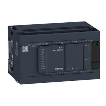
TM241C24R
Product ID:33919
Updated: 2026/10/16
Key Features
- 1Achieve up to 92% efficiency for significant energy cost reduction.
- 2Utilize a compact design to save valuable panel space.
- 3Operate globally with a wide 85-264VAC input voltage range.
- 4Improve power quality with built-in Power Factor Correction (PFC).
- 5Ensure long-term reliability with robust construction and a 5-year warranty.
Need a quote? Enter your quantity and get pricing fast.
Qty
Technical Specifications
Detailed engineering parameters
| Parameter | Value | Parameter | Value |
|---|---|---|---|
| Range of Product | Modicon M241 | Product or Component Type | Logic controller |
| [Us] rated supply voltage | 100...240 V AC | Discrete input number | 14, discrete input 8 fast input IEC 61131-2 Type 1 |
| Discrete output type | Transistor<br />Relay | Discrete output number | 6 relay<br />4 transistor 4 fast output |
| Discrete output voltage | 5...125 V DC relay output<br />5...250 V AC relay output<br />24 V DC transistor output | Discrete output current | 2 A relay output Q4...Q9)<br />0.1 A fast output (PTO mode) TR0...TR3)<br />0.5 A transistor output TR0...TR3) |
| Discrete I/O number | 24 | Maximum number of I/O expansion module | 7 (local I/O-Architecture)<br />14 (remote I/O-Architecture) |
| Supply voltage limits | 85…264 V | Network Frequency | 50/60 Hz |
| Discrete input logic | Sink or source | Discrete input voltage | 24 V |
| Discrete input voltage type | DC | Voltage state 1 guaranteed | >= 15 V input |
| Voltage state 0 guaranteed | <= 5 V input | Discrete input current | 5 mA input |
| Input impedance | 4.7 kOhm input | Response time | 50 µs turn-on, I0...I13 input |
| Configurable filtering time | 1 µs fast input | Discrete output logic | Positive logic (source) |
| Output voltage limits | 125 V DC relay output<br />30 V DC transistor output<br />277 V AC relay output | Maximum output frequency | 1 kHz transistor output<br />20 kHz fast output (PWM mode)<br />100 kHz fast output (PLS mode) |
| Accuracy | +/- 0.1 % 0.02…0.1 kHz fast output<br />+/- 1 % 0.1…1 kHz fast output | Protection type | Short-circuit protection transistor output<br />Short-circuit and overload protection with automatic reset transistor output<br />Reverse polarity protection transistor output<br />Without protection relay output |
| Reset time | 10 ms automatic reset output<br />12 s automatic reset fast output | Memory capacity | 64 MB system memory RAM |
| Data backed up | 128 MB built-in flash memory backup of user programs | Data storage equipment | <= 16 GB SD card optional) |
| Battery type | BR2032 lithium non-rechargeable 4 year(s) | Backup time | 2 years 77 °F (25 °C) |
| Execution time for 1 KInstruction | 0.3 ms event and periodic task<br />0.7 ms other instruction | Application structure | 4 cyclic master tasks<br />3 cyclic master tasks + 1 freewheeling task<br />8 external event tasks<br />8 event tasks |
| Realtime clock | With | Clock drift | <= 60 s/month 77 °F (25 °C) |
| Positioning functions | PTO 4 100 kHz) | Counting input number | 4 fast input (HSC mode) 200 kHz<br />14 standard input 1 kHz |
| Control signal type | A/B 100 kHz fast input (HSC mode)<br />Pulse/direction 200 kHz fast input (HSC mode)<br />Single phase 200 kHz fast input (HSC mode) | Integrated connection type | Non isolated serial link serial 1 RJ45 RS232/RS485<br />Non isolated serial link serial 2 removable screw terminal block RS485<br />USB port mini B USB 2.0 |
| Supply | Serial 1)serial link supply 5 V, <200 mA | Transmission rate | 1.2...115.2 kbit/s (115.2 kbit/s by default) 49.2 ft (15 m) RS485<br />1.2...115.2 kbit/s (115.2 kbit/s by default) 9.8 ft (3 m) RS232<br />480 Mbit/s 9.8 ft (3 m) USB |
| Communication port protocol | Non isolated serial link Modbus master/slave | Local signalling | for PWR 1 LED (green)<br /> for RUN 1 LED (green)<br /> for module error (ERR) 1 LED (red)<br /> for I/O error (I/O) 1 LED (red)<br /> for SD card access (SD) 1 LED (green)<br /> for BAT 1 LED (red)<br /> for SL1 1 LED (green)<br /> for SL2 1 LED (green)<br /> for bus fault on TM4 (TM4) 1 LED (red)<br /> for I/O state 1 LED per channel (green) |
| Electrical connection | removable screw terminal block for inputs and outputs pitch 5.08 mm)<br /> removable screw terminal block for connecting the 24 V DC power supply pitch 5.08 mm) | Maximum cable distance between devices | Unshielded cable <164.04 ft (50 m) input<br />Shielded cable <32.8 ft (10 m) fast input<br />Unshielded cable <164.04 ft (50 m) output<br />Shielded cable <9.8 ft (3 m) fast output |
| Insulation | Between supply and internal logic 500 V AC<br />Non-insulated between supply and ground | Marking | CE |
| Sensor power supply | 24 V DC 400 mA supplied by the controller | Surge withstand | 2 kV power lines (AC) common mode IEC 61000-4-5<br />2 kV relay output common mode IEC 61000-4-5<br />1 kV shielded cable common mode IEC 61000-4-5<br />1 kV power lines (AC) differential mode IEC 61000-4-5<br />1 kV relay output differential mode IEC 61000-4-5<br />1 kV input common mode IEC 61000-4-5<br />1 kV transistor output common mode IEC 61000-4-5 |
| Mounting support | Top hat type TH35-15 rail IEC 60715<br />Top hat type TH35-7.5 rail IEC 60715<br /> plate or panel with fixing kit | Height | 3.5 in (90 mm) |
| Depth | 3.7 in (95 mm) | Width | 5.9 in (150 mm) |
| Net Weight | 1.17 lb(US) (0.53 kg) | Standards | ANSI/ISA 12-12-01<br />CSA C22.2 No 142<br />CSA C22.2 No 213<br />IEC 61131-2:2007<br />Marine specification (LR, ABS, DNV, GL)<br />UL 508 |
| Product Certifications | RCM<br />cULus<br />CE<br />UKCA<br />DNV-GL<br />ABS<br />LR | Resistance to electrostatic discharge | 8 kV in air IEC 61000-4-2<br />4 kV on contact IEC 61000-4-2 |
| Resistance to electromagnetic fields | 9.1 V/m (10 V/m) 80 MHz...1 GHz IEC 61000-4-3<br />2.7 V/m (3 V/m) 1.4 GHz...2 GHz IEC 61000-4-3<br />0.9 V/m (1 V/m) 2 GHz...3 GHz IEC 61000-4-3 | Resistance to fast transients | 2 kV IEC 61000-4-4 power lines)<br />2 kV IEC 61000-4-4 relay output)<br />1 kV IEC 61000-4-4 serial link)<br />1 kV IEC 61000-4-4 input)<br />1 kV IEC 61000-4-4 transistor output) |
| Resistance to conducted disturbances | 10 V 0.15...80 MHz IEC 61000-4-6<br />3 V 0.1...80 MHz Marine specification (LR, ABS, DNV, GL)<br />10 V spot frequency (2, 3, 4, 6.2, 8.2, 12.6, 16.5, 18.8, 22, 25 MHz) Marine specification (LR, ABS, DNV, GL) | Electromagnetic emission | Conducted emissions 120...69 dBµV/m QP power lines)10…150 kHz IEC 55011<br />Conducted emissions 63 dBμV/m QP power lines)1.5…30 MHz IEC 55011<br />Conducted emissions 79 dBμV/m QP/66 dBμV/m AV power lines)0.15…0.5 MHz IEC 55011<br />Conducted emissions 73 dBμV/m QP/60 dBμV/m AV power lines)0.5…300 MHz IEC 55011<br />Radiated emissions 40 dBμV/m QP class A 10 m)30…230 MHz IEC 55011<br />Conducted emissions 79...63 dBμV/m QP power lines)150…1500 kHz IEC 55011<br />Radiated emissions 47 dBμV/m QP class A 10 m)230…1000 MHz IEC 55011 |
| Immunity to microbreaks | 10 ms | Ambient air temperature for operation | 14…122 °F (-10…50 °C) vertical installation)<br />14…131 °F (-10…55 °C) horizontal installation) |
| Ambient Air Temperature for Storage | -13…158 °F (-25…70 °C) | Relative humidity | 10…95 %, without condensation in operation)<br />10…95 %, without condensation in storage) |
| IP degree of protection | IP20 with protective cover in place | Pollution degree | 2 |
| Operating altitude | 0...6561.68 ft (0...2000 m) | Storage altitude | 0.0000000000…9842.5 ft (0…3000 m) |
| Vibration resistance | 3.5 mm 5…8.4 Hz symmetrical rail<br />3 gn 8.4…150 Hz symmetrical rail<br />3.5 mm 5…8.4 Hz panel mounting<br />3 gn 8.4…150 Hz panel mounting | Shock resistance | 15 gn 11 ms |
Specifications may be subject to change without notice
Still deciding on TM241C24R?
Our engineers can confirm stock, price, and lead time for this schneider part.
Get a no-obligation quote in 1 minute.